Introduction
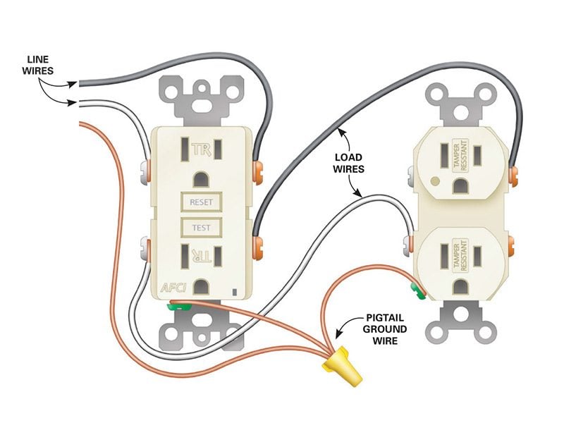
A Wiring Outlets Diagram is a visual representation of the electrical connections between outlets in a building. It provides a clear overview of how the outlets are wired together, which is essential for understanding the electrical system of a property.
Why Wiring Outlets Diagram are essential
Wiring Outlets Diagram are crucial for several reasons:
- Helps electricians and technicians understand the layout of electrical outlets in a building
- Aids in troubleshooting electrical problems
- Ensures that outlets are wired correctly and safely
How to read and interpret Wiring Outlets Diagram effectively
When looking at a Wiring Outlets Diagram, it’s important to pay attention to the following:
- The location of each outlet
- The type of wiring used (e.g., copper, aluminum)
- The connections between outlets (e.g., series, parallel)
- The presence of any switches or junction boxes
How Wiring Outlets Diagram are used for troubleshooting electrical problems
Wiring Outlets Diagram can be a valuable tool for diagnosing and fixing electrical issues. By following the diagram, technicians can:
- Identify the source of a problem (e.g., a faulty outlet, a loose connection)
- Trace the flow of electricity through the system
- Determine the best course of action for repairs
Importance of safety
Working with electrical systems can be dangerous, so it’s crucial to follow safety precautions when using Wiring Outlets Diagram. Some tips and best practices include:
- Always turn off the power before working on electrical outlets
- Use insulated tools to prevent electric shocks
- Wear protective gear, such as gloves and goggles
- Consult a professional if you are unsure about any aspect of the wiring system
Wiring Outlets Diagram
How to Wire an Outlet and Add an Electrical Outlet (DIY) | Family Handyman

A Comprehensive Guide To Gfci Outlet Wiring Diagrams – Wiring Diagram

how to wire multiple outlets together – Wiring Work
/wiring-electrical-receptacle-circuits-through-a-receptacle-1152787-01-2a9a43dca2d04d6597dcfb791a548ff9.jpg?strip=all)
WIRING DIAGRAM FOR MULTIPLE OUTLET – YouTube

How to Install Electrical Outlets in the Kitchen | The Family Handyman

How To Electrical Wiring A House
