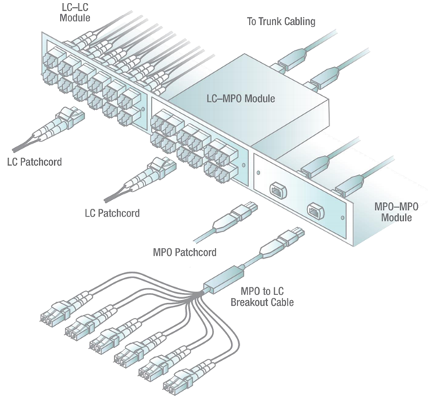
When it comes to setting up and maintaining a network infrastructure, understanding how to properly wire and organize connections is crucial. This is where Patch Panel Wiring Diagram comes in handy. These diagrams provide a visual representation of how cables are connected to a patch panel, making it easier to troubleshoot issues and make changes when needed.
Why Patch Panel Wiring Diagrams are Essential
- Helps in organizing and labeling network connections
- Aids in troubleshooting connectivity issues
- Ensures consistency in wiring configurations
- Facilitates future upgrades and modifications
Reading and Interpreting Patch Panel Wiring Diagrams
When looking at a Patch Panel Wiring Diagram, it’s important to understand the symbols and labels used. Here are some key points to keep in mind:
- Each cable is represented by a line with specific colors or patterns for easy identification
- Ports on the patch panel are usually numbered for reference
- Labels may indicate the type of cable, such as Cat5e or Cat6
- Arrows show the direction of the connection
Using Patch Panel Wiring Diagrams for Troubleshooting
When faced with connectivity issues, Patch Panel Wiring Diagrams can be a lifesaver. By following the diagram, you can quickly identify any faulty connections or missing cables. Here’s how you can use the diagram for troubleshooting:
- Check for loose or disconnected cables
- Verify that cables are plugged into the correct ports
- Look for any damaged cables or connectors
- Use a cable tester to determine if a cable is faulty
Importance of Safety
Working with electrical systems, including patch panels, can be dangerous if proper precautions are not taken. Here are some safety tips to keep in mind:
- Always turn off power before working on any wiring
- Use insulated tools to prevent electric shock
- Avoid working in wet conditions or with wet hands
- Double-check connections before powering up the system
Patch Panel Wiring Diagram
Patch Panel Wiring Guide
Rj45 Patch Panel Wiring Diagram – Organicify

How To Use a Fiber Optic Patch Panel – Teleweaver

[DIAGRAM] 110 Patch Panel Wiring Diagram – MYDIAGRAM.ONLINE
![Patch Panel Wiring Diagram [DIAGRAM] 110 Patch Panel Wiring Diagram - MYDIAGRAM.ONLINE](https://i1.wp.com/i.stack.imgur.com/JvaKo.jpg)
How to Create a Patch Panel Wiring Diagram: Step-by-Step Example

Patch Panels: A Complete Guide
