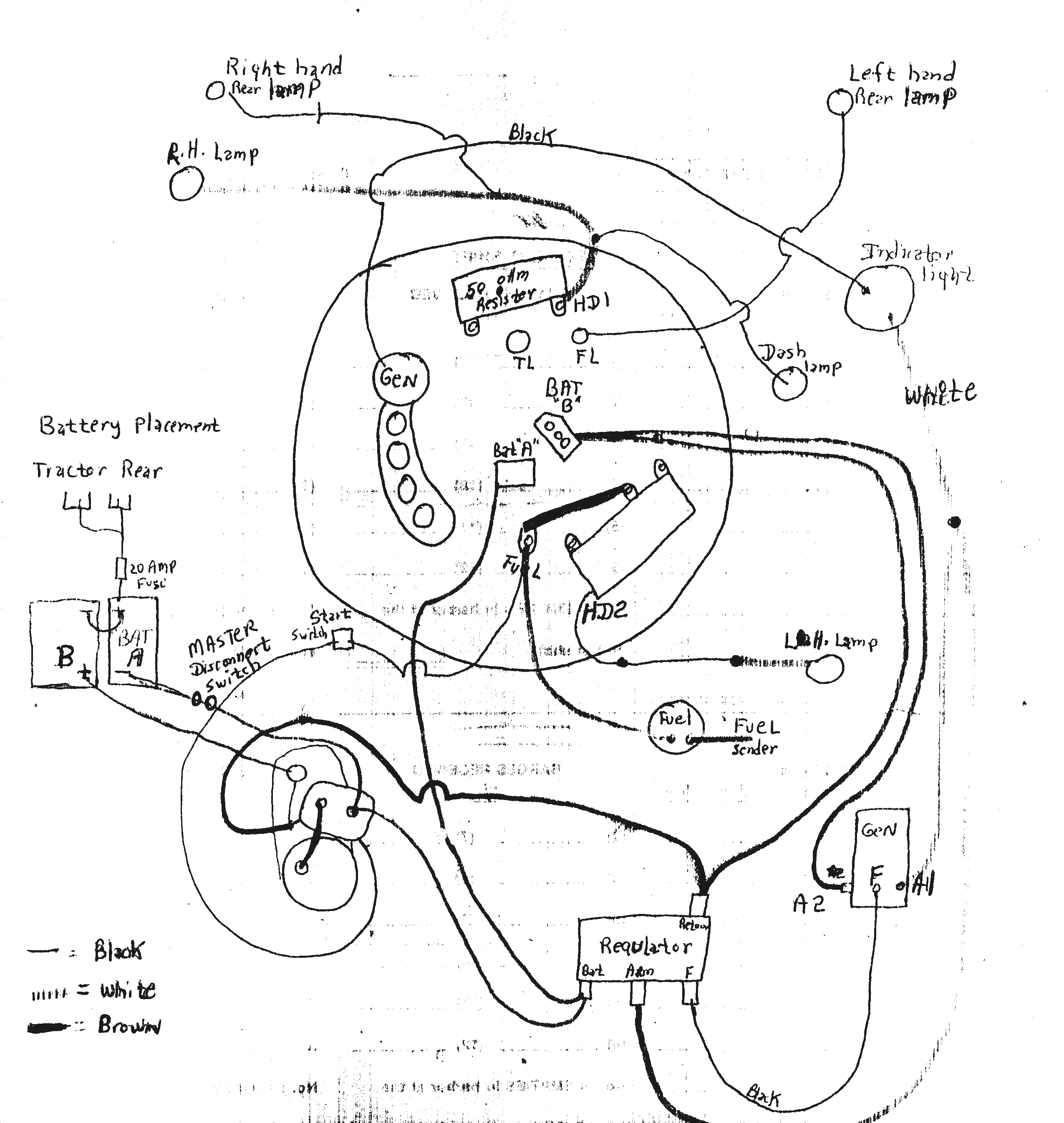
When it comes to understanding the electrical system of a diesel vehicle, the Diesel Ignition Switch Wiring Diagram is an essential tool. This diagram provides a detailed illustration of the wiring connections for the ignition switch, helping mechanics and technicians to troubleshoot electrical issues efficiently.
Why Diesel Ignition Switch Wiring Diagrams are Essential
1. Helps identify the correct wiring connections for the ignition switch.
2. Guides technicians in locating and repairing electrical faults effectively.
3. Ensures proper installation of new components or replacement parts.
Reading and Interpreting Diesel Ignition Switch Wiring Diagrams
1. Identify the symbols used in the diagram for different components.
2. Follow the color-coding of wires for accurate connections.
3. Understand the flow of electricity from the battery to the ignition switch.
Using Diesel Ignition Switch Wiring Diagrams for Troubleshooting
1. Locate the ignition switch on the diagram and trace the wiring connections.
2. Check for any loose connections, damaged wires, or faulty components indicated in the diagram.
3. Use a multimeter to test the continuity of the circuits and determine any electrical issues.
Importance of Safety
When working with electrical systems and using wiring diagrams, it is crucial to prioritize safety. Here are some safety tips and best practices:
- Always disconnect the battery before working on any electrical components.
- Use insulated tools to prevent electric shocks.
- Avoid working on the electrical system in wet or humid conditions.
- Refer to the vehicle’s service manual for specific safety precautions.
Diesel Ignition Switch Wiring Diagram
Ignition Switch Wiring Diagram Diesel Engine – paceinspire

kubota diesel ignition switch wiring diagram – MeagenEshel

[DIAGRAM] For Universal Diesel Ignition Wiring Diagrams – MYDIAGRAM.ONLINE
![Diesel Ignition Switch Wiring Diagram [DIAGRAM] For Universal Diesel Ignition Wiring Diagrams - MYDIAGRAM.ONLINE](https://i1.wp.com/i2.wp.com/route6x6.com/howto/wiring/wiring6.jpg)
kubota diesel ignition switch wiring diagram – MeagenEshel

Ignition Switch Wiring Diagram Diesel Engine – paceinspire
Diesel Tractor Ignition Switch Wiring Diagram – Wiring Site Resource
