Connector Wiring Diagrams are an essential tool for anyone working with electrical systems. These diagrams provide a visual representation of the connections between various components in a circuit, making it easier to understand how the system is wired and how it functions.
Why Connector Wiring Diagrams are Essential
Connector Wiring Diagrams are essential for a number of reasons:
- Helps in understanding the layout of electrical systems
- Aids in identifying faulty connections or components
- Assists in planning and executing modifications or upgrades
- Ensures compliance with safety standards and regulations
Reading and Interpreting Connector Wiring Diagrams
Reading and interpreting Connector Wiring Diagrams can be daunting for beginners, but with some guidance, it can become much easier. Here are some tips:
- Start by familiarizing yourself with the symbols and abbreviations used in the diagram
- Follow the flow of the circuit from the power source to the output
- Pay attention to the color-coding and labeling of wires and connectors
- Refer to the legend or key provided in the diagram for additional information
Using Connector Wiring Diagrams for Troubleshooting
Connector Wiring Diagrams are invaluable when it comes to troubleshooting electrical problems. By following the diagram and tracing the connections, you can quickly identify the source of the issue and take appropriate action. Some common uses include:
- Checking for continuity and proper voltage levels
- Testing individual components for faults
- Verifying proper grounding and insulation
- Isolating and resolving short circuits or open circuits
Importance of Safety
When working with electrical systems and using Connector Wiring Diagrams, safety should always be a top priority. Here are some safety tips and best practices to keep in mind:
- Always turn off the power before working on any electrical system
- Use insulated tools and equipment to prevent shocks or short circuits
- Wear appropriate protective gear, such as gloves and safety glasses
- Double-check your work before re-energizing the system to avoid potential hazards
Connector Wiring Diagram
Hopkins Trailer Connector Wiring Diagram | Wiring Diagram

6 Pin Trailer Connector Wiring Diagram – Free Wiring Diagram

Wat is 15-Polig (ISO 12098)? – TRALERT®

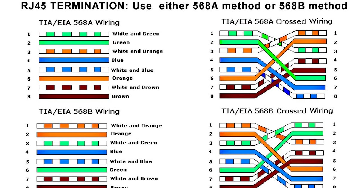
Rj45 Connector Wiring Diagram

Cat 5 Connector Wiring Utube – Wiring Diagrams Hubs – Rj45 Wiring

2003 7.3l Idm Connector Wiring Diagram
