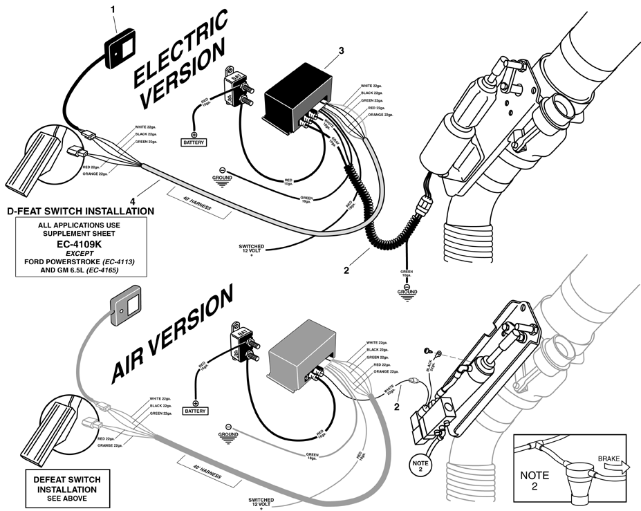
Welcome to the world of Brake Motor Wiring Diagrams! These diagrams are essential tools for understanding the intricate electrical systems that power brake motors. By following these diagrams, you can effectively troubleshoot issues, make repairs, and ensure that your brake motor is running smoothly.
Why Brake Motor Wiring Diagrams are Essential
Brake Motor Wiring Diagrams are crucial for several reasons:
- They provide a visual representation of the electrical connections in the brake motor, making it easier to understand how the system works.
- They help technicians identify components and their respective functions, which is essential for troubleshooting and maintenance.
- They ensure that electrical connections are properly made, reducing the risk of short circuits or other electrical hazards.
Reading and Interpreting Brake Motor Wiring Diagrams
When reading a Brake Motor Wiring Diagram, it’s important to pay attention to the following:
- Identify the components and their symbols on the diagram to understand how they are connected.
- Follow the flow of electricity from the power source to the motor to ensure all connections are correct.
- Check for any labels or color codes that indicate the function of each wire or component.
Using Brake Motor Wiring Diagrams for Troubleshooting
Brake Motor Wiring Diagrams are invaluable when it comes to troubleshooting electrical problems. By following the diagram, you can:
- Locate the source of the issue, whether it’s a faulty connection, a broken wire, or a malfunctioning component.
- Verify that all connections are correct and in working order to eliminate potential causes of the problem.
- Make necessary repairs or replacements based on the information provided in the diagram.
Importance of Safety
When working with electrical systems and using wiring diagrams, safety should always be the top priority. Here are some safety tips and best practices to keep in mind:
- Always turn off the power supply before working on any electrical components to prevent electric shock.
- Use insulated tools and equipment to reduce the risk of electrical hazards.
- Wear appropriate personal protective equipment, such as gloves and safety goggles, to protect yourself from potential injuries.
- If you are unsure about any aspect of the wiring diagram or the electrical system, consult a professional technician for assistance.
Brake Motor Wiring Diagram
Engine Brake Wiring Diagram – Wiring Diagram and Schematics

Clutch Brake Motor Connection Diagram Rectifier Module – YouTube

Motor brake rectifier connection diagram | Engineers CommonRoom

Engine Brake Wiring Diagram – Wiring Diagram and Schematics
