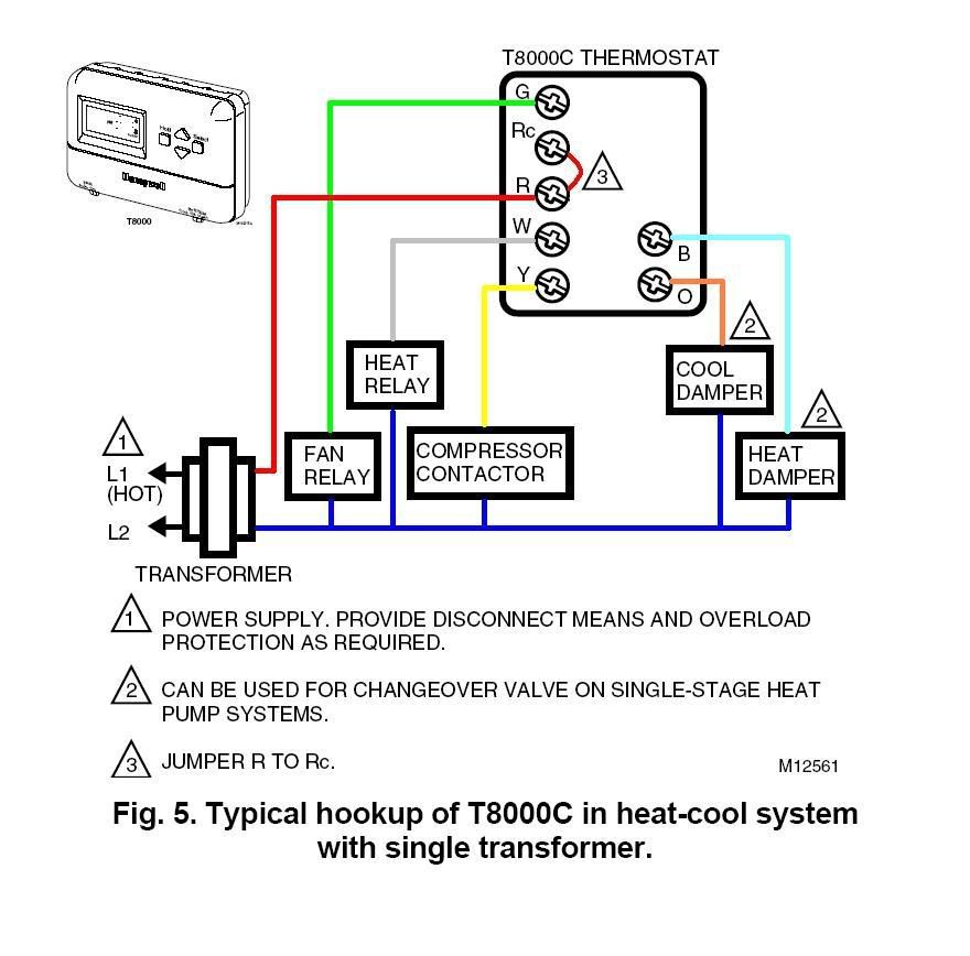
When it comes to understanding and working with electrical systems in HVAC equipment, a 24v Thermostat Wiring Diagram is an invaluable tool. This diagram provides a visual representation of how the various components in a thermostat system are connected and powered. By following the wiring diagram, technicians can easily troubleshoot issues, install new equipment, or make repairs with confidence.
Why are 24v Thermostat Wiring Diagrams essential?
- Provide a clear and organized layout of the wiring connections
- Ensure proper installation of new equipment
- Aid in troubleshooting electrical issues
- Help prevent damage to equipment due to incorrect wiring
How to read and interpret 24v Thermostat Wiring Diagrams effectively
When looking at a wiring diagram, it’s important to understand the symbols and color-coding used to represent different components. Typically, wires are color-coded to indicate their function, such as red for power, white for heat, green for fan, etc. Additionally, symbols like lines, dots, and numbers are used to show how the components are connected.
Using 24v Thermostat Wiring Diagrams for troubleshooting electrical problems
- Identify the source of the issue by tracing the wiring connections
- Check for loose or damaged wires that may be causing a problem
- Compare the actual wiring to the diagram to see if there are any discrepancies
- Use a multimeter to test for continuity and proper voltage levels
It’s important to exercise caution when working with electrical systems and using wiring diagrams. Here are some safety tips and best practices to keep in mind:
- Always turn off the power before working on any electrical components
- Wear appropriate protective gear, such as gloves and safety glasses
- Double-check all connections before turning the power back on
- If you are unsure about any aspect of the wiring diagram, consult with a professional technician
24v Thermostat Wiring Diagram
24v Thermostat Wiring Diagram

24v Thermostat Wiring Diagram

Wiring Diagram For Ac Unit Thermostat

Installation And Wiring Of A 24V Low Voltage Thermostat! Step

thermostat wiring use Thermostat furnace voltage heating transformer
