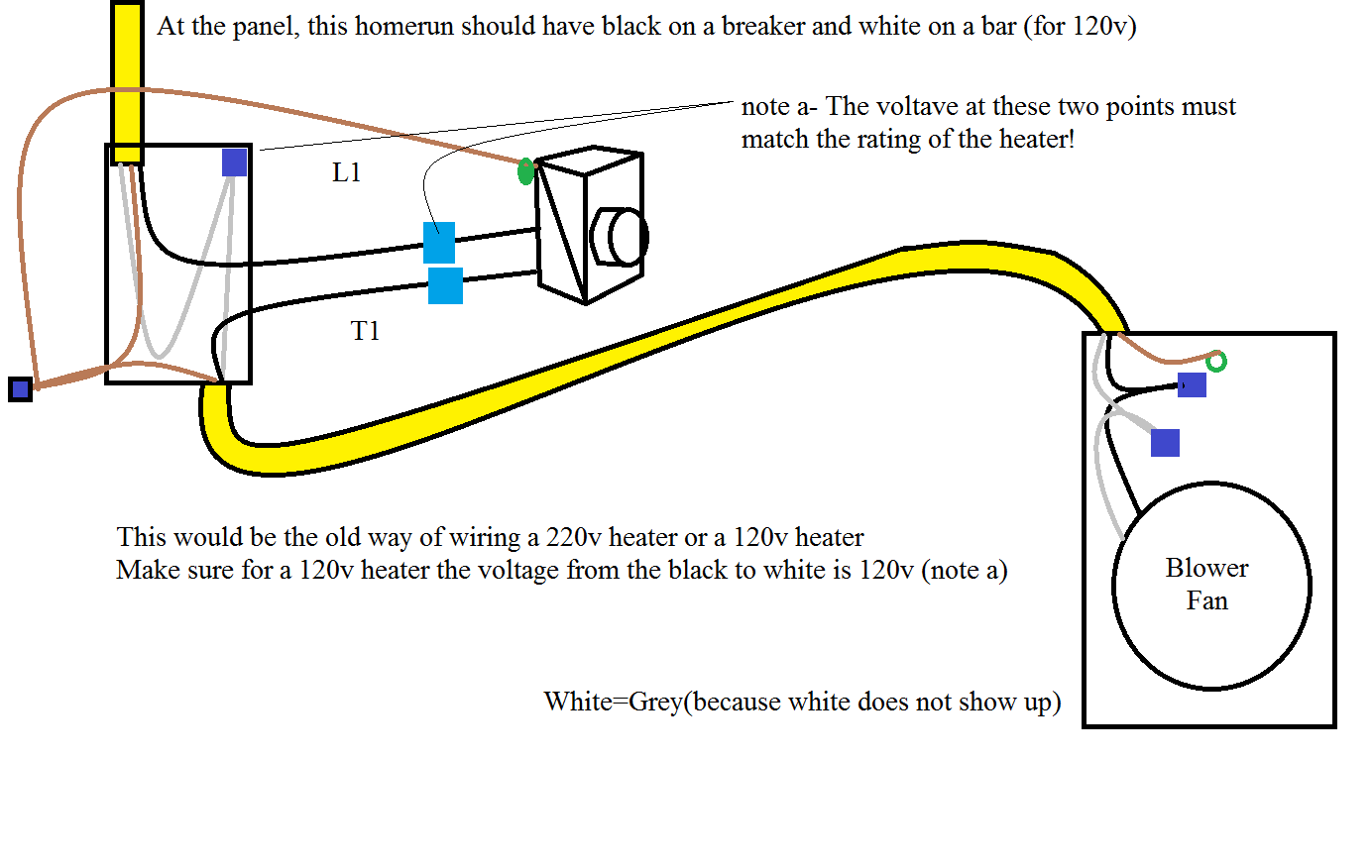
When it comes to understanding the inner workings of electrical systems, a 120v Motor Wiring Diagram is an essential tool. This diagram provides a visual representation of the electrical connections for a 120v motor, helping users to understand how the motor is wired and how different components are connected.
Why are 120v Motor Wiring Diagrams Essential?
1. Ensure proper installation: A wiring diagram ensures that the motor is wired correctly, preventing potential damage or malfunction.
2. Troubleshooting: With a wiring diagram, users can easily identify and fix any issues that may arise with the motor.
3. Safety: Following a wiring diagram helps to ensure that all electrical connections are made safely and according to code.
How to Read and Interpret 120v Motor Wiring Diagrams
1. Identify components: Familiarize yourself with the symbols and labels used in the diagram to understand the various components of the motor.
2. Follow the flow: Trace the path of the electrical connections from the power source to the motor to understand how electricity flows through the system.
3. Pay attention to colors: Wiring diagrams often use color-coding to differentiate between different wires. Make sure to follow the color-coding key provided in the diagram.
Using 120v Motor Wiring Diagrams for Troubleshooting
1. Identify potential issues: Look for any disconnected or damaged wires, loose connections, or other abnormalities in the wiring diagram that may be causing the problem.
2. Follow the wiring sequence: Check the sequence of connections in the diagram to ensure that everything is wired correctly and in the right order.
3. Consult a professional: If you are unsure about how to interpret the wiring diagram or troubleshoot the motor, it is always best to seek help from a qualified electrician.
Safety Tips for Working with 120v Motor Wiring Diagrams
- Always turn off the power before working on any electrical system.
- Use insulated tools to prevent electrical shocks.
- Double-check all connections before turning the power back on.
- Wear appropriate safety gear, such as gloves and safety goggles, when working with electrical systems.
- If in doubt, consult a professional electrician for assistance.
120v Motor Wiring Diagram
Step-by-Step Guide: How to Wire a 120v Motor – Wiring Diagram Included

120v Ac Capacitor Motor Reversing Switch Wiring Diagram

120v Motor Wiring Diagram – Wiring Diagram and Schematic

120v Blower Motor Wiring Diagram

Types of Single Phase Induction Motors | Single Phase Induction Motor

120v Ac Capacitor Motor Reversing Switch Wiring Diagram
